TM 9-2350-261-20-1
2 0 0 A M P F U L L F I E L D C H A R G E T R O U B L E S H O O T I N G
INITIAL SETUP
Tools:
General Mechanic’s Tool Kit (Item 30, App D)
Multimeter (Item 43, App D)
Electrical Connector Pliers (Item 44, App D)
Alternator Test Kit (Item 74.1, App D)
Personnel Required:
Unit Mechanic
References:
See your -10
Equipment Conditions:
Engine stopped (see your -10)
Carrier blocked (see your -10)
Ramp lowered (see your -10)
All radios and heaters OFF (see your -10)
Battery box cover removed (page 13-3) or
battery drawer open (page 13-24)
1. Disconnect batteries (page 13-2).
NO
2. Check all electrical connectors. harnesses. and cannon
plugs before connecting alternator test kit.
3. Are connectors and cannon plugs tight and pins in place
in harnesses?
I
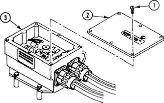
1. Remove six screws (1) and cover (2) from voltage
regulator (3).
2. Connect multimeter to clean unpainted surface and
vehicle ground.
3. Does multimeter read 0.5 ohms or less?
1. Tighten or repair connec-
tions, cannon plugs, and
harnesses. Use electrical
connector pliers.
2. Repeat charging system
operational check
(page 3-64.4).
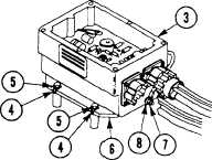
1. Ensure lock washers (4) and
screws (5) are tight on
plate (6).
2. Tighten nut (7) securing
ground lead (8) to
regulator (3).
3. Install cover and screws on
voltage regulator.
4. Repeat charging system
operational check
(page 3-64.4).
G O T O N E X T P A GE
Change 1
3-64.9