
TM 9-2350-247-20-2
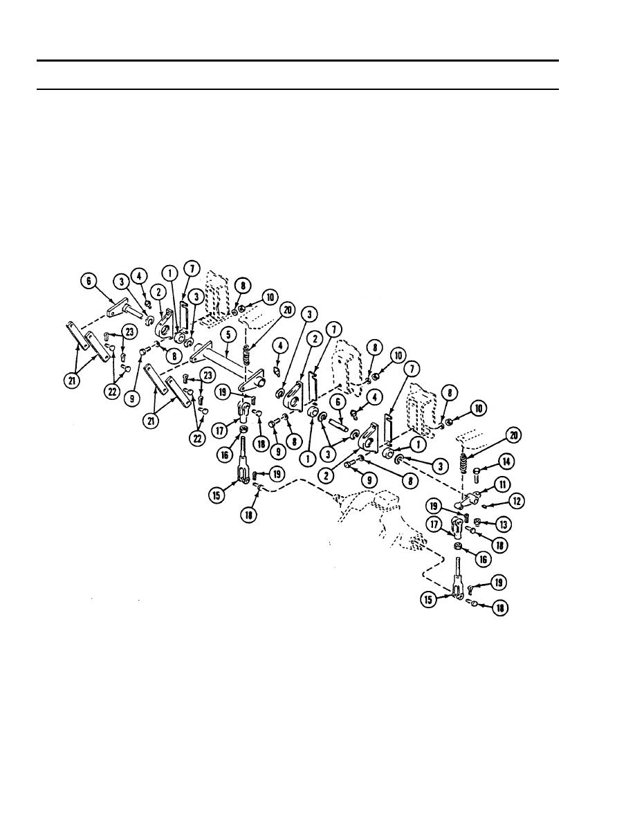
REPLACE STEERING CONTROL/LINKAGE (M548A1) -- Continued
0366 00
NOTE
Make sure rod end shows at hole in lower clevis (15).
9.
Install two jam nuts (16) and upper clevises (17) on two lower clevises (15). Secure clevises with jam nuts (16).
10. Place assembled clevis pair (15) and assembled clevis pair (17) in carrier with lower clevises (15) on two differential
arms.
11. Secure clevises (15) to differential arms with two clevis pins (18) and new cotter pins (19). Secure upper clevises (17) to
actuator arm (11) and outer shaft (5) with two clevis pins (18) and new cotter pins (19).
12. Install return spring (20) from actuator arm (11) to hull bracket. Install return spring from outer shaft (5) to hull bracket.
13. Install four connecting links (21) to inner shaft (6) and outer shaft (5) with two clevis pins (22) and new cotter pins (23).
0366 00-8

