
TM 9-2350-247-20-2
REPLACE T130 TRACK DRIVE SPROCKETS, CUSHIONS, AND CARRIER
0357 00
ASSEMBLY -- Continued
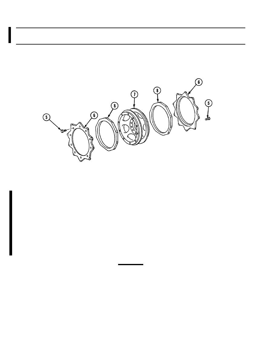
Remove 20 lock bolts (5) and 2 drive sprockets (6) from carrier (7). Discard lock bolts.
3.
4.
Remove two rubber cushions (8) from carrier (7).
5.
If needed, repeat Steps 1 - 4 for other drive sprocket carrier assembly.
INSTALLATION
Place two cushions (1) on carrier (2). Center short flat areas between mounting holes in carrier rim. Press on cushion
1.
until firmly seated against flange of carrier.
NOTE
Make sure you use matching sprockets. New longer life sprockets are thicker and have one
wear indicator on both sides of the sprocket teeth. Use as a set when replacing them on a
carrier assembly.
NOTE
There are different length bolts for securing the sprockets to the carrier and the carrier
assembly installation to the final drive.
2.
Place two drive sprockets (3) on carrier (2). Secure with 20 new lock bolts (4). TIGHTEN LOCK BOLTS TO 110-115
LB-FT (149-156 NM) TORQUE. Use torque wrench.
CAUTION
Drive sprocket mounting bolts must be proper length, or final drive output seal will be damaged.
3.
Place drive sprocket carrier assembly (5) on final drive (6). Secure with 10 new lock bolts (7) (bolt length 1 3/4 in (4
cm)). TIGHTEN LOCK BOLTS TO 170-190 LB-FT (230-258 NM) TORQUE. Use torque wrench.
4.
Mark drive sprockets (3) and cushions (1) for rotation check after road test.
Change 1

