
TM 9-2350-247-20-2
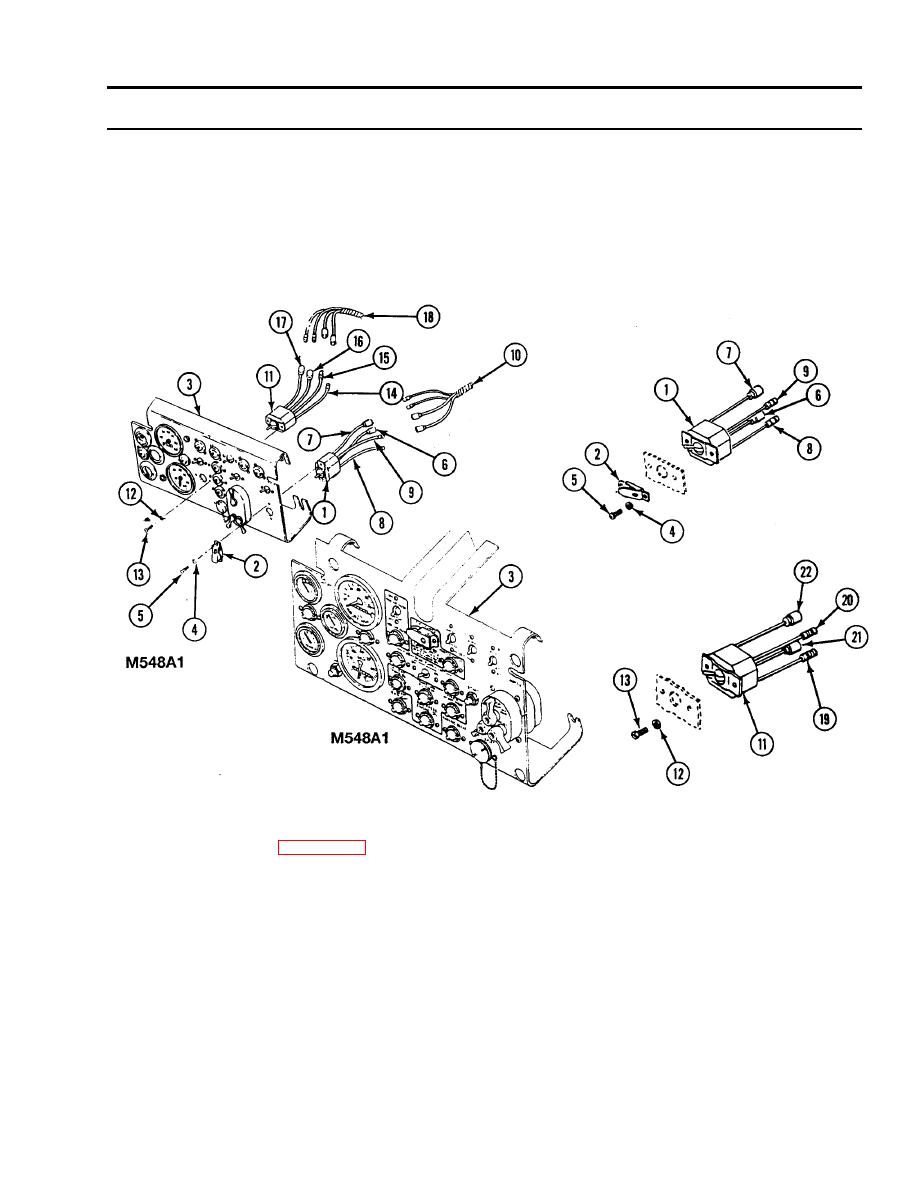
REPLACE BILGE AND FUEL PUMP SWITCHES -- Continued
0261 00
INSTALLATION
1.
Place fuel pump switch (1) and guard (2) on instrument panel (3). Secure with two washers (4) and screws (5).
2.
Connect circuit leads 76 (6), 14A (7), 77-78 (8), and 74 (9) to wiring harness (10).
3.
Place bilge pump switch (11) in instrument panel (3). Secure with two washers (12) and screws (13).
4.
Connect circuit leads 452 (14), 451 (15), 450B (16), and 450 (17), to wiring harness (18). For M548A3, connect 452A
(19), 451A (20), 450B (21), and 450 (22).
FOLLOW-THROUGH STEPS
1.
Install instrument panel (WP 0256 00).
2.
Turn MASTER SWITCH ON (see your -10).
3.
Check bilge and fuel pump switches. If pumps go on, switches are OK.
4.
Turn MASTER SWITCH OFF (see your -10).
END OF TASK

