
TM 9-2350-247-20-2
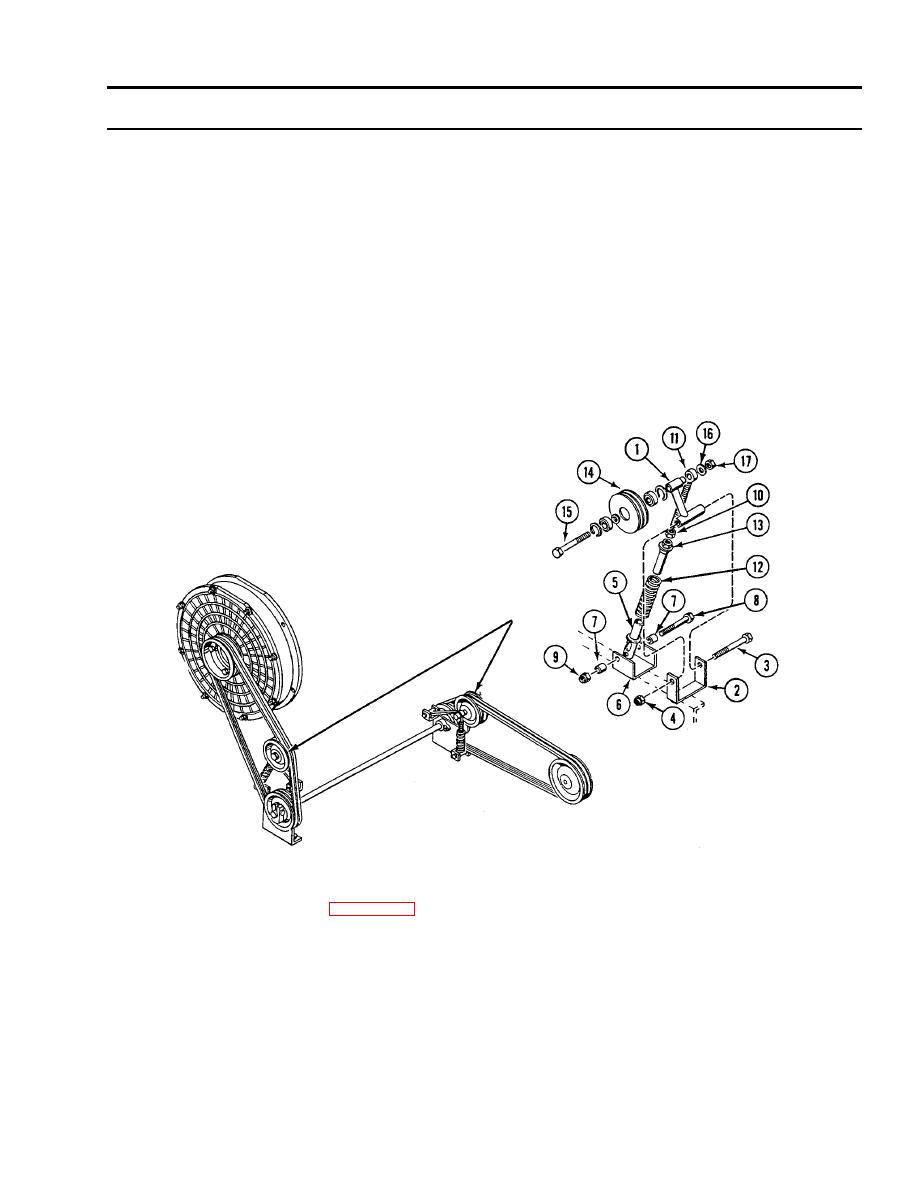
REPLACE FAN DRIVE BELT IDLER ADJUSTING LINKAGE (M548A1) -- Continued
0230 00
INSTALLATION
NOTE
Front or rear idler adjusting linkages are installed the same way.
1.
Install support arm (1) in bracket (2). Secure with screw (3) and new lock nut (4).
2.
Install adjusting sleeve (5) in bracket (6). Secure with two spacers (7), screw (8), and new lock nut (9).
3.
Install new jam nut (10) on rod end (11).
4.
Install spring (12), adjusting nut (13), jam nut (10), and rod end (11) on adjusting sleeve (5).
5.
Secure idler pulley (14) to rod end (11) and support arm (1) with screw (15), washer (16), and new lock nut (17). Tighten
nut to 50-55 lb-ft (68-75 Nm) torque.
FOLLOW-THROUGH STEPS
1.
Install and adjust fan drive belts (WP 0226 00).
2.
Start engine (see your -10).
3.
Check fan drive belt adjusting linkage for proper installation.
4.
Stop engine (see your -10).
5.
Lower center seat (see your -10).
6.
Install power plant upper rear access door (see your -10).
END OF TASK

